Multistage Amplifier
After having gained some hands on experience in working with transistors, I was required to design and build a multistage amplifier using FETs and BJTs. I always look forward to projects like these and I was really excited and happy to see everything come along as I was working on it.
Planning
I was provided a detailed specification that my design had to accomplish, for example, I couldn't use resistors below the value of 1kohms, there was a specific gain, output and input impedances that I was required to achieve. Planning mainly involved setting up deadlines to complete the various tasks and keeping track of progress. I was required to complete the project within 3 weeks, each week included 2 x 3hr labs sessions (Due to covid situation I couldn't access the labs oustide these hours)
Action
There were 4 stages in the amplifier, the first one being a FET source follower which was used for having a high input impedance, the other two stages were BJTs which were used for the gain and the final stage was a phase splitter using a BJT. I spent a couple of lab sessions completing the design calculations. It wasn't an easy task, as I had to undergo the same calculations over and over again, trying to estimate the resistor values. However, after my 21st trial, I was finally able to achieve the specification. After having completed the calculations, I simulated the circuit on Proteus. Due to careful considerations during the design phase, only two resistors were required to be changed and for the rest I used the same calculated values. For the final prototyping stage, I built the circuit on breadboard using the different components and performed the testing. I recorded all the measurements in an excel sheet which was the report that was required to be submitted. I also added all the tolerance calculations in the report in order to justify the variations in the measurement values.
Result
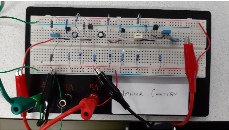
The design worked quite well. I was able to achieve all the design specifications. The amount of time that I had spent on the design calculation was worth it as I did not have to change much components during the simulation stage. I scored an 87% overall for the project. The picture below shows the final breadboard circuit that I built.
Learnings and Improvements
This project helped me gain further experience in designing, building and testing analogue electronic systems. I was able to learn about cascaded amplifiers and the different considerations one needs to understand and implement in the design specifically when doing the calculations for the components. I have now understood the importance of the designing phase of any electronic systems, the amount of time and effort put into this phase reflects throughout the project. Spending some time carefully designing the circuit actually aids in creating an efficient system at the end.
Next time, I would use an excel sheet for the design calculations, using excel formulas really makes it easier to perform the design calculations.